![]()

Tools Required
Torch, Good welder (230V at least), Sawzall and many blades, Grinder and lots of grinding disks, Drill and 1/2" & 1/4 " long drill bits, A good assortment wrenches and sockets, Pitman arm removing tool, Impact gun & ratchet, Air grinder, Paint, grease Gun, 4 or more Jack Stands
 |
 |
 |
 |
| Fig 1.0 | Fig 1.1 | Fig 1.2 | Fig 1.3 |
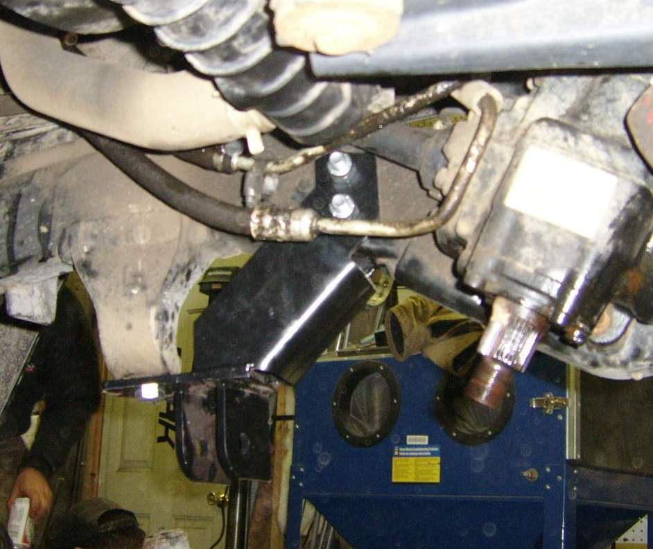
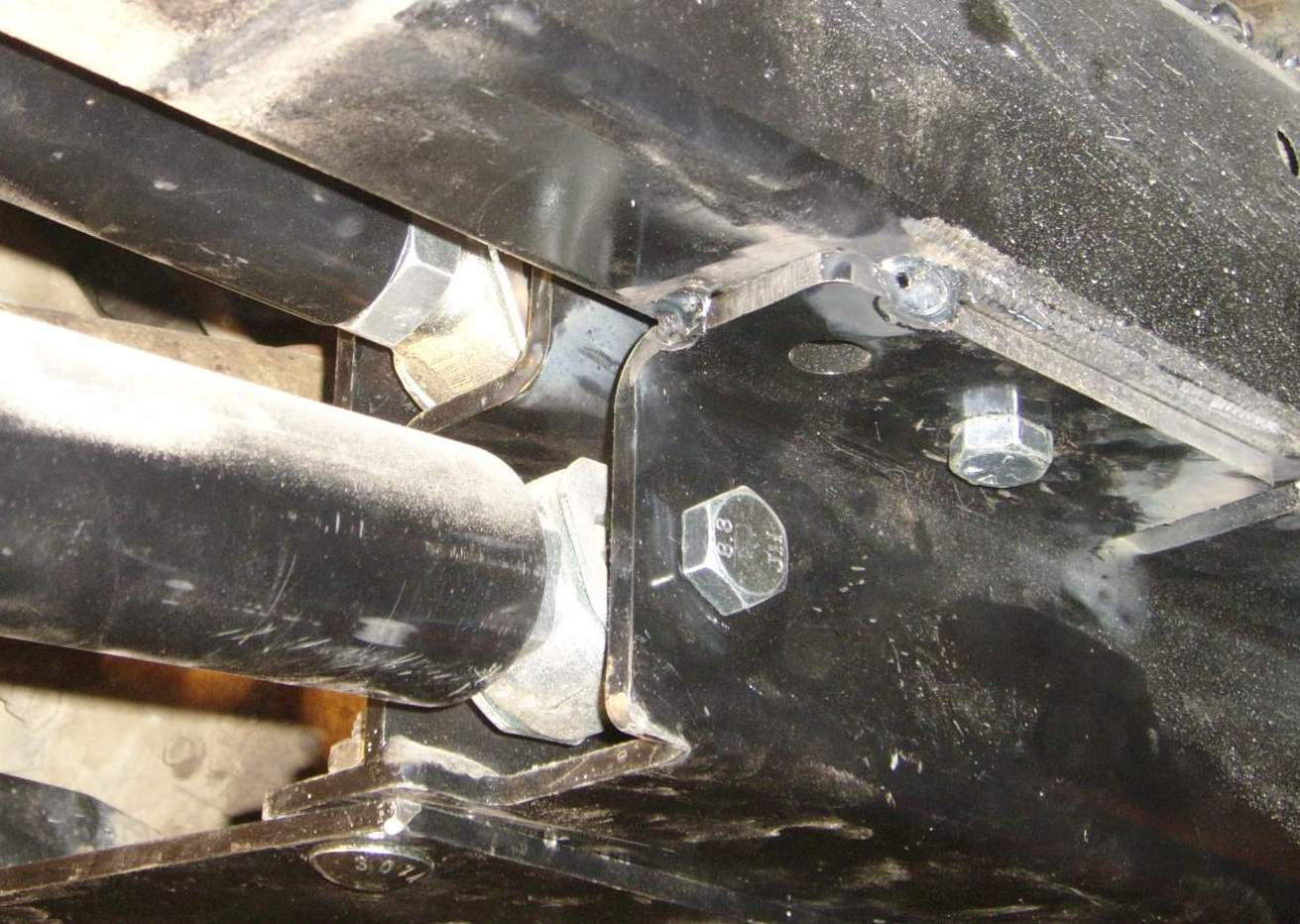
To get things moving we started on the skid plate, unscrew your locker pumps (Rubicon model only) and move them out of the way for the time being, take the skid plate off, but make sure to keep your OEM hardware for alignment purposes and to reuse. Now grind the 6 tabs off where the stock plate bolts up to the frame (Fig 1.0) but make sure you don't grind all the way down to the frame, leave at least 1/8 so that the bolt bung does not push through up into the frame. The reason for this is due to the new replacement skid plate actually grabs the frame from the top and bottom adding a huge amount of frame structure. On the Rubicon version the locker lines & pump will need to be relocated before you install the skid plate. Start with the drivers side Frame rail bracket (Contains the Upper and lower bracket welded to it) The passenger side mount only has the rear upper and lower control arm brackets welded to it. Paint the areas you grinded and put in the new bracket in * Note* On 97 to 02 TJ versions the most forward hole in the new bracket lines up with the most front OEM skid plate bolt hole but on the 2003 TJ the first OEM skid plate bolt goes into the second hole in the new bracket (Fig 1.1) To make things easier we clamped both sides down and tacked them (Fig 1.2) then we drilled the new holes using the brackets as a guideline and then bolted the brackets up on both sides with the hardware supplied by your Kit (Fig 1.4) While the Skid plate is off, now is the best time to cut the stock exhaust off from the Cat back as it will only be in the way and you will need a custom setup afterwards anyway. The new Exhaust on this project was installed by one of Universityofjeep.ca Sponsors Pipes Performance and they did an amazing job for a great price.
 |
 |
 |
 |
 |
| Fig 1.4 | Fig 1.5 | Fig 1.6 | Fig 1.7 | Fig 1.8 |
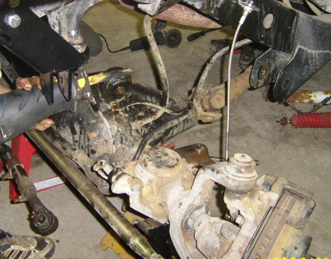
Next you will need to move along to the front end, now that your frame rails are set to take the skid plate and control arms. Start by undoing all your bolts for the track bar, drag link, shocks, brake lines, remove stock coil springs and pitman arm, lower control Arms, upper control arms. We had a bit of a problem on one of our lower control arm bolts, it was so seized that we were getting a full turn out on the wrench from top of the axle around to the other side without the bushing breaking free from the bolt, we tried even tried some fluids but eventually cut the bolt from the inside of the control arm bracket. Last but not least the pitman arm and as always Pitman arms are usually a pain in the ass, so make sure you have a good tool for this job or a stubborn friend that will not give up to take this task on if you brake the tool you have. Next was the new track bar relocation bracket it fits securely up against the frame rail very nicely so best is to hold it up mark your holes to be drilled on the inside of the frame rail and out. Due to it obviously being in a tight spot to drill from the inside we used the markings to pre-drill the inside of the frame rail bracket with a small bit that fit into the angle air grinder (Fig 1.4) for a guide when you drill from the the other side of the frame (Fig 1.5) with a ½ inch drill bit. Now once completed bolt the bracket in as well as using the factory Track bar bolt bracket (We had to drill this out with a 9/16 Drill bit for bolt clearance) as shown in (Fig 1.6) The upper control arm bracket located on the axle will need to have the stock original bushing removed. As usual the bushing was seized and to make things easy we just cut down the from the top of the bushing as close to the axle mount running the blade along side of the Molded tab (Fig 1.7) and then punched it out with a 5lb sledge and a long tube to push it out of the axle mount (Fig 1.8), then install the new upper axle bushing supplied from rock krawler (Fig 1.9) The only thing we found is you may want to cut the bolts off a little when bolting this bushing as they are a little long. We used a little Lithium Grease to assemble the new bushing as shown in the picture to help stop the water and elements in there down the road.
 |
 |
 |
 |
| Fig 1.9 | Fig 2.0 | Fig 2.1 | Fig 2.2 |
Now is the time to brake out the grinder and start cutting off all the OEM lower control arm brackets from the frame do your best to make a clean cut without damaging the frame to much. Grind off the lower control arm brackets. We used allot of small grinding disks to cut along the welds just down to the frame and then jam a Chisel in between the frame and the control arm bracket while massaging it with the tool of choice the "5lb sledge" Soon as you can get it to the point where it will separate from the frame bend it back and forth till it comes off. Do this for all the frame mounted lower control arm brackets (Fig 2.0) Now that you have all four of the front and rear lower control arm brackets grinded off and clean of any sharp edges you should paint it. Shown in (Fig 2.1 ) is a basic comparison of the OEM stock arms and the serious beef that Rock Krawler supplies (Fig 2.2). The control arms supplied in this kit are some major heavy duty replacements to the stock versions or more than any other basic kit out there that I have installed, wait until you get a hold of one of these arms and you will know what we mean. With the front end completely disassembled and ready for the installation you must check the lengths of the arms to ensure they are correct. They do come pre assembled however some minor adjustments need to be made. Use the chart below to measure your joints from center to center of bolt positioning.
|
Reference Lengths TJ/LJ Front Lower Control Arm Assembled Length = 40.00" TJ Rear Lower Control Arm Assembled Length = 29.31" LJ Rear Lower Control Arm Assembled Length = 39.188" TJ/LJ Triangulated 4 Link Assembly = 22.19" (Short rear Uppers) TJ Triangulated 4 Link Assembly = 36.00" (Long rear Uppers) LJ Triangulated 4 Link Assembly = 45.76" Front Upper Torque Arm Assembled Length = 42.782" TJ/LJ 4.0" Front Track bar Assembled Length = 32.34" TJ/LJ 5.5" through 7.0" Front Track Bar Assembled Length = 33.3375" TJ/LJ 8.0" Front Track Bar Assembled Length = 33.50"
Slide a bolt through the one end on both LCA when you have the first end measurement completed on.
|
|
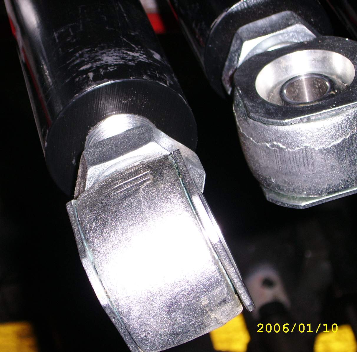
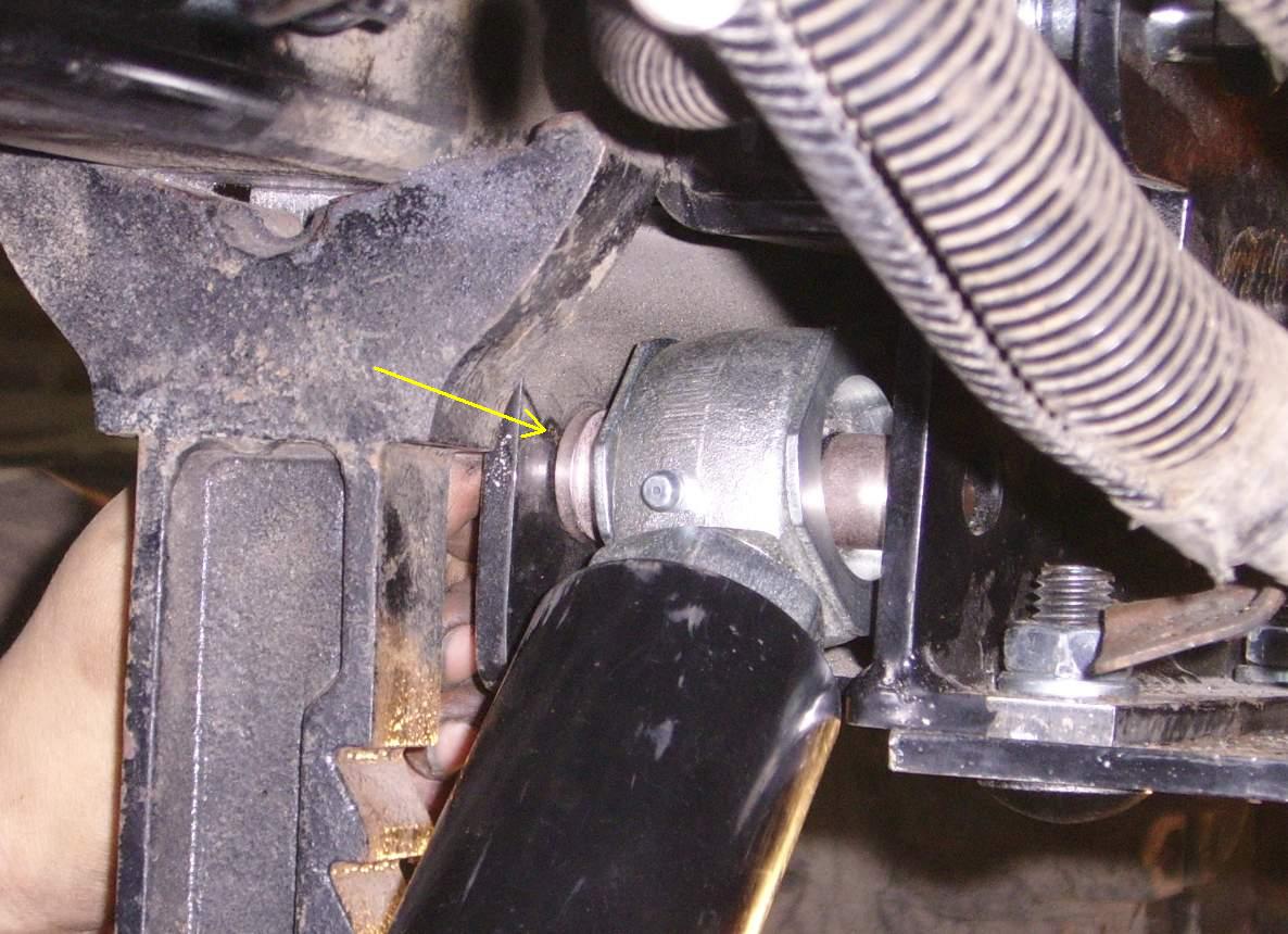
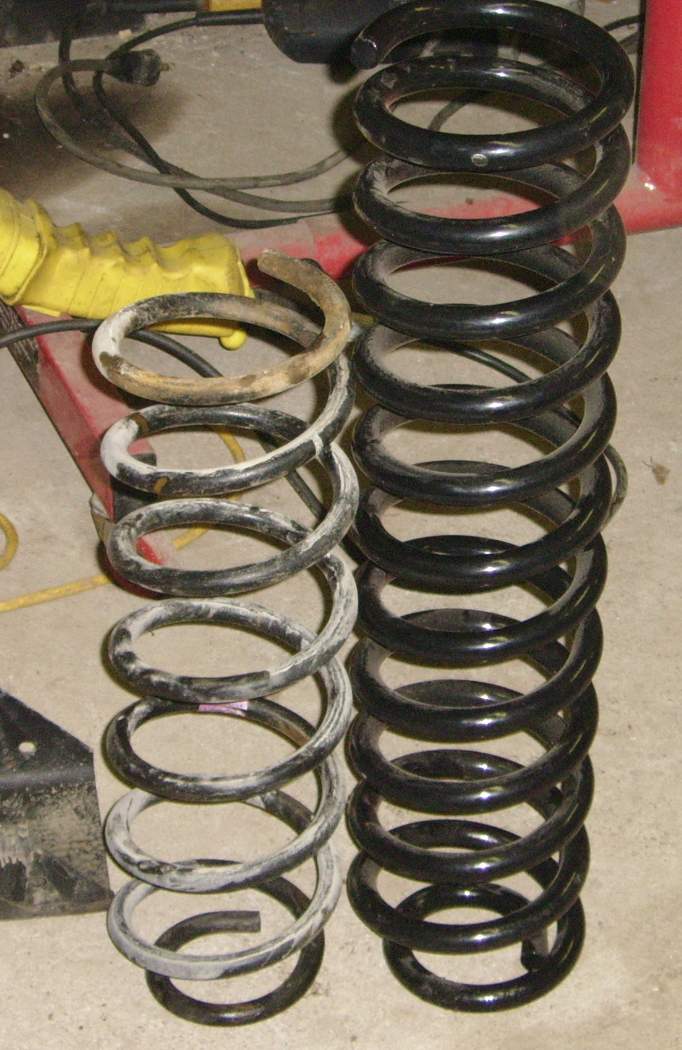
Now that you have all your measurements done it is time to start installing everything on the front end. Make sure to install the lower control arms with the skid plate mount end first then the axle end. Make sure that you have the long misaligned spacers with the shoulder faced towards the outside of the mounts (Fig2.4) as well as the grease nipple pointed up when installing them into the frame mounted skid plate on both sides. Once you get all the lower control arms in as well as the uppers you will need to also install the Supplied Rock Krawler track bar. Be sure to have the bushing on the axle end and the rod end into the new bracket supplied that you previously installed (Fig 1.6) Install your shocks *Note* For 7.0"-8.0" kits it is advised to have a bar pin eliminator to transition the shock travel for larger size tires to support the increased un-sprung weight of a larger tire. Install the supplied sway bar link assemblies to the stock sway bar (Fig 2.7) and then slide in your new coil springs (look at the difference Fig 2.6). Be sure that there is at least 5/8 of thread engaged on your Sway bar links for safety reasons. Install the new stainless steel brake lines supplied with the kit as well.
 |
 |
 |
 |
 |
| Fig 2.4 | Fig 2.5 | Fig 2.6 | Fig 2.7 | Fig 2.8 |
FINALLY the front is completed and you are ready to start on the rear. Start by making sure that you undo the bolts for the rear track bar as well as the shocks. Take the lower control arms off as well as the uppers and retain the stock OEM hardware for this. Remove the coils, brake lines and get ready to remove the rear axle to make things easier for the install and fabrication required. The kit was offered with a bolt on triangulated mount that basically bolts onto the back of the axle where the OEM diff guard is located with other brackets for the control arms, however we optioned for the weld in rear cradle for better strength and performance over time. The kit picture shown above "center" displays the bracket but fails to show the weld in rear cradle. Once you have everything removed and out of the way now remove the axle and put on some stands to prep for installation of the new brackets and 4 Link system. Shown below are the two mounts available from Rock Krawler.
 |
 |
|
Bolt in Cradle Mount with hardware |
Weld in Cradle mount for extra strength and durability |
 |
 |
 |
| Fig 2.9 | Fig 3.0 | Fig 3.1 |
Once again as mentioned you will need to cut the rear lower control arm mounts off the frame (Fig 2.9) With the axle removed start by making sure you only cut off what is required (upper control arm brackets as well as the rear track bar bracket) As shown in (Fig 3.0) We used a set of torches for this for an easy cut and some basic grinding to clean up the mounting surface for the cradle. Once the axle is cleaned up and smooth place the cradle on top making sure it is centered properly from left to right and the holes in the cradle obviously face forward. Align the back edge of the cradle flush in line with the machined surface of the rear differential (diff cover mounting surface) then weld into place with a good solid weld on both sides on every mounting surface with the axle you can get at (Fig 34 to 35) Now get the axle back under the jeep after you have cleaned the welds and painted the axle.
 |
 |
 |
| Fig 3.2 | Fig 3.3 | Fig 3.4 |
 |
 |
 |
| 3.5 | 3.6 | 3.7 |
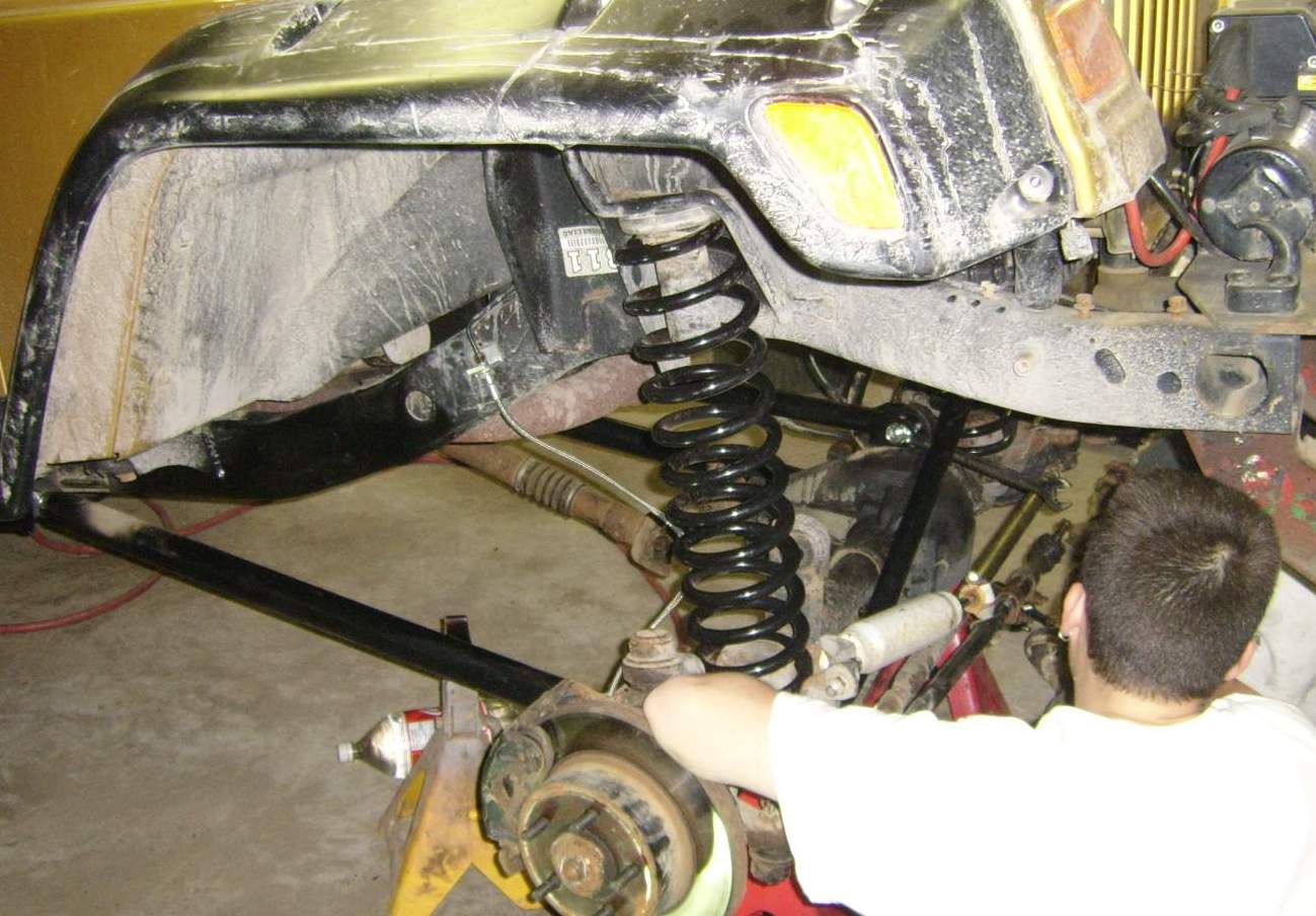
We started with the driver & passenger side upper & lower control arms fitting them into the new mounting surfaces located on the skid plate Example: (Fig 3.6) With a friend at the other side of the axle supporting the weight & helping to move the axle back and forth while you fit the lower control arms into the stock OEM lower axle brackets as well as the fitting the triangulated upper arms into the center axle Cradle mount giving you your first look at the new 4 link system. Now you can fit the new supplied coil springs (Fig 3.9) and start doing the basic re-installation of the shocks, sway bar and links but be sure to install with the rod offset towards the frame on the rear links and don't forget your brakes (Bleed brake lines if axle removed)
 |
 |
 |
|
| Fig 3.8 | Fig 3.9 | Fig 4.0 | |
 |
 |
| Fig 4.1 | Fig 4.2 |
Steering correction
The only thing we did not get with the new kit was the upgraded steering that is also offered by Rock Krawler. Although the equipment from RK is great we just didn't expect the steering to rub so much without this upgrade. When you turned the wheel to the left & right the steering Tie Rod End would rub on the track bar bracket that's welded on the axle when turning all the way to the right. We decided that we had to get the steering corrected before we threw the tires on and got a look at this newly lifted Jeep. Next we cut the stock OEM stock mount off the upper part of the Dana 30 (Fig 4.3) so we could fab up our own version of the corrected steering stabilizer bar mount that would be out of the way from the steering. Shown in (Fig 4.4) we cleaned up the axle and cut a 1/4 Thick plate molded to the curves of the coil mount and the axle edge for a good weld, then used a chunk of flat stock making the bends to create the same size (inside diameter) as required to fit the steering stabilizer shock shown in (Fig 4.5 & 4.6) We tested it again and was a great Modification that turned out good.
 |
 |
 |
 |
| Fig 4.3 | Fig 4.4 | Fig 4.5 | Fig 4.6 |
Now that everything is installed be sure to grab a good working market and go through every bolt you touched to tighten to specified torque and then checking the top of the bolt off with the marker to be sure you get everyone. Its also recommended with any lift kit basically to check the status of your bolts periodically for the next couple days re-tightening if required. Now for the end result ! see pictures below. The jeep currently has 33" TSL Boggers but a set of 37" Trexus MT's were purchased and installed after this write up. When we update with some flexing pics you will see the finished product.
 |
 |
 |
|
Rock krawler follow up by Sebastian Oct 22 2005
It’s been few months since we installed my new 7inch rock krawler long arm system on my 2003 Jeep Rubicon. The day to day ride of the lift is great and handles way better then stock ever did on the road, even with that much lift. I also took out my rear sway bar, b/c there is almost no roll with those springs, on the other hand, b/c of that they’re a bit stiff and the ride is not as soft as it used to be. As far as off-roading goes, the kit is awesome I can’t believe the flex I get. Even off camber situation it performs amazing. Although I like the lift I already had a small problem where my steering pitman arm got bent on the trail (that was fixed within few days due to the customer service support from Rock Krawler), rock krawler sent me another one without hesitation and said it was a bad batch of heat treating from the manufacture.
Over all I would get the same lift all over again, I’m really enjoying it and recommend to anyone that is looking for a hardcore kit for there TJ.
(Approx 6 months after install)
|
|
Retail Resources: Rock Krawler Suspensions Inc. 518-270-9822
|
 |
